
Views: 0 Author: Site Editor Publish Time: 2026-07-26 Origin: Site


The most common point of failure in load-bearing equipment, commercial casework, and industrial workstations is rarely the shaft of the leg itself; it is the connection point where the leg meets the substrate. Specifying an Adjustable Leg with an inadequate mounting plate leads to lateral instability, wobble, shear stress fractures, fastener pull-out, and ultimately, compromised safety or product lifespan under heavy loads. Selecting the optimal mounting plate requires evaluating load distribution geometry, fastener spacing, thread pitch compatibility, and thread engagement depth. This guide breaks down how to assess mounting plate designs to ensure maximum stability for industrial, commercial, and heavy-duty furniture applications. We will look at the exact mechanics of load transfer, the physical geometry of different plate styles, and the specific installation methods required to prevent catastrophic failure on the shop floor or in high-traffic commercial environments.
A larger mounting plate does not guarantee stability unless the fastener holes are positioned at the outer edges to maximize the lever arm against lateral forces.
Geometry Dictates Application: Square and circular plates offer superior omnidirectional stability, while corner-mount and U-bracket designs provide specialized resistance against shear loads in casework.
Thread Engagement & Pitch Matter: The stability of a leveling foot relies heavily on the thickness of the mounting plate's central boss and the thread profile (UNC vs. Metric coarse); insufficient thread depth leads to stripping and axial deflection under dynamic loads.
Substrate Compatibility: The strongest mounting plate design will still fail if the fastening method (e.g., direct wood screws vs. steel threaded inserts or T-nuts) is mismatched to the substrate material.
Dynamic vs. Static Load Profile: Selecting a plate requires assessing not just vertical compression, but also dynamic lateral shear forces—such as when a heavy machine or furniture leg is dragged or slid across a floor.
Defining the success criteria for a stable connection between an adjustable support and a base structure starts with understanding load vectors. A mounting plate must handle more than just static weight. It acts as the primary structural bridge transferring forces from the floor up into the equipment frame. If this bridge is weak, the entire structure becomes compromised, regardless of how thick the actual leg shaft is.
Mounting plates distribute direct downward weight, known as axial load, across the substrate surface. However, the true test of stability comes from resisting sideways forces, or radial loads. When pushing a heavy workbench or machine, the lateral shear stress concentrates at the mounting interface. A poorly designed plate will flex or allow the fasteners to tear through the base material. You have to account for the fact that equipment gets bumped, leaned on, and shifted. The plate must absorb these impacts without transferring the bending moment directly into the threads of the leg.
The physical distance from the center of the adjustable leg to the outermost fasteners dictates the plate's ability to resist tipping torque and bending moments. Fasteners placed too close to the center thread create a short lever arm, offering minimal resistance to wobble. Pushing the fastener holes to the extreme edges of the plate maximizes leverage, locking the leg rigidly against the substrate. Think of it like using a longer wrench to break a stubborn bolt; a wider fastener spread gives the plate a mechanical advantage against the forces trying to rip it out of the wood or metal base.
Relocating a heavy unit without lifting it introduces severe dynamic drag forces. As the foot drags across the floor, the bottom of the leg catches, creating a massive bending moment at the mounting plate. This action attempts to pry the leading edge of the plate away from the substrate while driving the trailing edge upward. Robust plate geometry and secure fastening are critical to surviving these structural stress vectors. We see this constantly in commercial kitchens and factory floors where equipment is dragged for cleaning.
Assess the total static weight of the equipment to determine the required axial load capacity.
Calculate the potential lateral shear force based on how frequently the unit will be moved or bumped.
Measure the available mounting surface area to determine the maximum possible fastener spread.
Evaluate the floor surface; rough concrete generates higher drag forces than smooth tile.
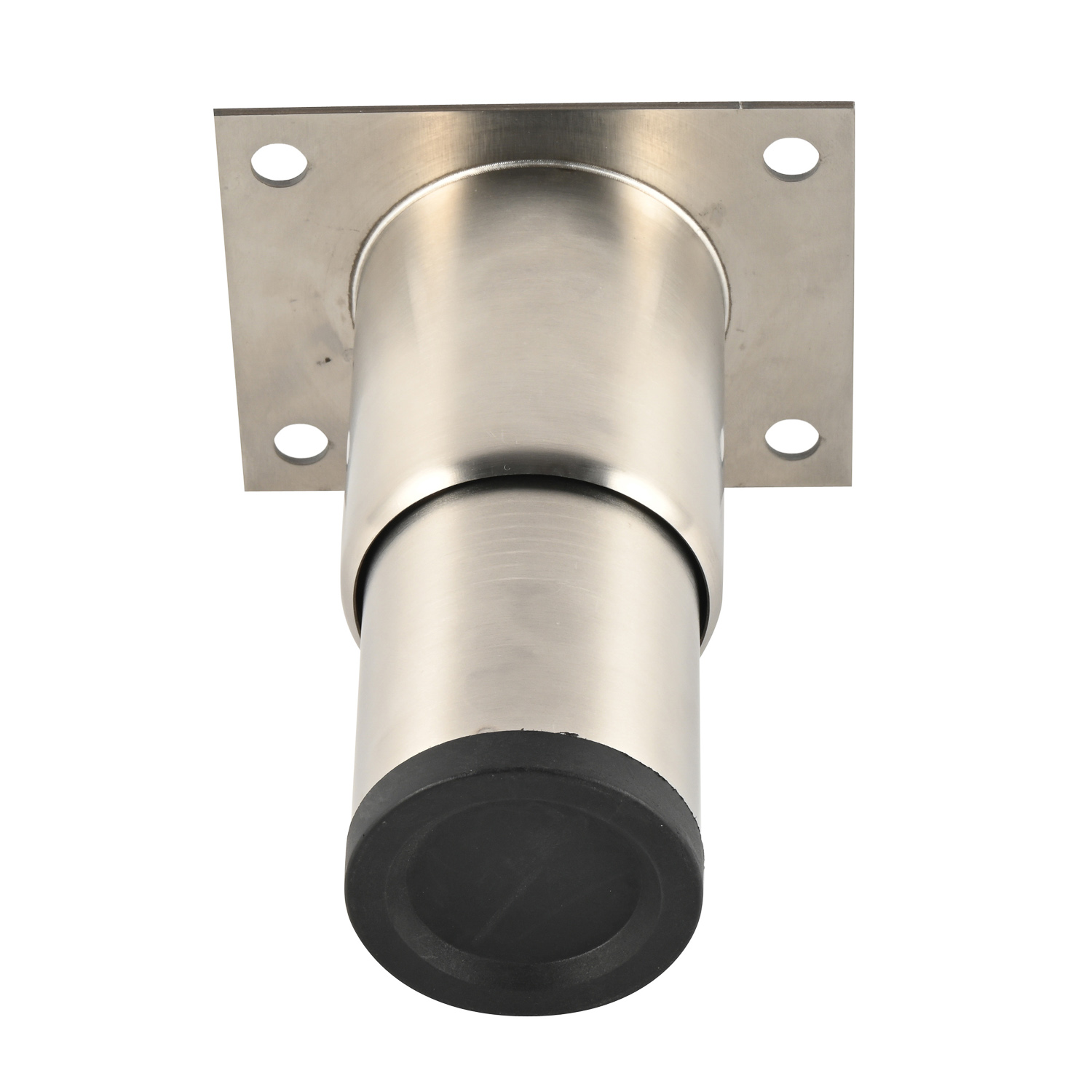
Different applications demand specific plate shapes to manage unique stress profiles. Understanding the geometric advantages of each design ensures the correct specification for the task. You cannot just slap a square plate on every piece of equipment and expect it to hold up under dynamic stress.
Square and rectangular plates feature four-point fastening, symmetrical load distribution, and standardized corner screw patterns. This geometry provides predictable stability for freestanding equipment. It remains the ideal choice for standard applications where omnidirectional lateral forces are moderate, effectively spreading the load across a wide footprint. When installing these, always ensure the fasteners are driven perfectly perpendicular to the substrate to avoid uneven stress on the screw heads.
Triangular plates utilize a right-angle alignment, three-point fastening, and a flush-fit design. They are often engineered for the industry-standard 32mm system used in modular cabinetry. This design maximizes stability in cabinet corners and casework by transferring loads directly into the vertical structural panels rather than relying solely on the weaker horizontal bottom substrate. This is a massive advantage when dealing with particleboard or MDF, which have terrible screw retention on their flat faces.
Circular plates feature a continuous radius and equidistant circular fastener spacing, commonly referred to as a bolt circle. This shape eliminates weak vectors or directional shear vulnerabilities. It is highly effective for heavy machinery, food processing equipment, and heavy cylindrical bases where forces can originate from any angle. The lack of corners means there is no single point of concentrated stress when the equipment is subjected to rotational forces.
U-bracket designs offer multi-planar fastening, securing to both the bottom face and the vertical sides of the substrate. This configuration provides exceptional resistance to shear stress and high-impact lateral loads. It stands as the premier choice for top-heavy equipment, mobile carts, or dynamic environments where side impacts are frequent. By wrapping around the material, the bracket physically prevents the substrate from splitting under heavy lateral loads.
Plate Geometry | Primary Advantage | Best Substrate Application | Shear Resistance Level |
|---|---|---|---|
Square / Rectangular | Symmetrical load distribution | Solid wood, metal frames | Moderate |
Triangular / Corner | Transfers load to vertical panels | MDF, particleboard casework | High (in corners) |
Circular | Omnidirectional shear resistance | Heavy steel machinery bases | Very High |
U-Bracket | Multi-planar fastening | Plywood carts, top-heavy frames | Extreme |
Beyond shape, the physical construction of the plate determines its ultimate failure point. Evaluating material properties and thread specifications is non-negotiable for heavy-duty applications. A plate might look strong, but if the metal is too thin or the threads are poorly cut, it will fail under load.
Assessing gauge requirements based on load ratings is essential. A 10-gauge steel plate will deflect under loads that a 7-gauge plate can easily support. Stamped gussets or welded reinforcement ribs play a structural role in preventing plate deflection under heavy compression, maintaining the perpendicular alignment of the leg. When a plate bends, it changes the angle of the leg, which immediately introduces a bending moment into the threaded shaft, leading to rapid failure.
Evaluating the central tapped hole versus a welded hex nut or an integrated extruded boss reveals the plate's holding power. A minimum of 3 to 4 full threads of engagement is required to prevent a Leveling Foot from stripping or cross-threading under vibration. Thin plates without an extruded boss lack the necessary depth for secure thread engagement. If you only have one or two threads holding the load, any lateral movement will rip the threads right out of the plate.
The choice between metric threads (e.g., M8, M10, M12) and Unified Coarse (UNC) threads impacts stability, micro-adjustability, and resistance to backing out under vibration. Coarse threads offer higher resistance to cross-threading and stripping in heavy-load scenarios, while fine threads allow for more precise height adjustments. For industrial environments with heavy vibration, coarse threads are generally preferred because they are less likely to vibrate loose over time.
Countersunk holes allow fastener heads to seat flush, which significantly improves shear resistance by preventing lateral slip. Slotted holes provide tolerance adjustments during installation but compromise absolute structural rigidity compared to fixed, round holes. The application determines which hole design is appropriate. If you need absolute rigidity, avoid slotted holes entirely and drill precise pilot holes for fixed round-hole plates.
Selecting the right plate requires aligning the hardware capabilities with the physical demands of the environment. You have to look at the whole system: the floor, the leg, the plate, and the substrate.
These environments require high static load capacity, extreme vibration resistance, and chemical exposure resistance. The solution involves thick-gauge zinc-plated circular or square steel plates with welded heavy-duty central bosses and through-bolt fastening compatibility to handle the intense operational stresses. You cannot rely on wood screws here; you must use through-bolts with heavy washers or nyloc nuts on the opposite side of the frame to ensure the plate never pulls loose.
Casework demands clean aesthetics, complete concealment, corner support, and resistance to dragging. Specifying a Furniture Leg with steel wrap-around brackets or heavy-duty triangular corner plates utilizing threaded inserts rather than standard wood screws ensures long-term durability against high traffic and frequent cleaning cycles. Threaded inserts distribute the load across a wider area of the particleboard, preventing the catastrophic pull-out that happens with standard screws.
Applications on sloped or uneven floors require articulation to handle angled surfaces without bending the connection point. Wide-stance rectangular plates paired with an articulating, ball-and-socket leveling foot absorb off-axis forces, keeping the mounting plate flat against the substrate while the foot adjusts to the floor. If you use a rigid foot on an uneven floor, the entire weight of the machine will rest on one edge of the foot, sending a massive bending force straight up into the mounting plate.
Identify the substrate material (wood, metal, composite) to determine the correct fastener type.
Select a plate geometry that maximizes fastener spread within the available mounting area.
Verify the thread pitch of the leg matches the tapped boss on the mounting plate exactly.
Install the plate using the appropriate torque settings to avoid crushing the substrate or stripping the fasteners.
Adjust the leg to the minimum required height to keep the center of gravity low and reduce the lever arm effect.
Even the best hardware fails if installed incorrectly or pushed beyond its design limits. Recognizing common failure modes allows for proactive mitigation on the job site.
Avoid using short wood screws in MDF, particleboard, or softwoods. These materials lack the density to hold threads under lateral shear. Specify threaded inserts, heavy-duty T-nuts, or through-bolting with backing plates for high-stress applications to distribute the pull-out force through the entire thickness of the substrate. If you are mounting to a hollow metal tube, use rivet nuts (rivnuts) to provide a secure, threaded anchor point for the machine screws.
Calculate the maximum required height adjustment prior to specification. Extending a foot too far reduces thread engagement inside the mounting plate, exponentially increasing the moment arm and risking catastrophic lateral failure under load. Keep extensions within the manufacturer's recommended limits. If you need more height, buy a longer leg or build a taller base; do not just unthread the foot until it is hanging by two threads.
When mounting steel plates to aluminum framing or utilizing components in damp or hygienic environments, galvanic corrosion will rapidly degrade the connection. Specify isolating nylon gaskets or marine-grade 304/316 stainless steel to prevent structural degradation and maintain joint integrity over time. In food processing facilities, ensure the mounting plate has no exposed crevices where bacteria can accumulate, and use sealed, hygienic leveling feet.
Failure Mode | Root Cause | Field Mitigation Strategy |
|---|---|---|
Fastener Pull-Out | Using wood screws in MDF/Particleboard | Switch to threaded inserts or through-bolts |
Thread Stripping | Insufficient engagement depth in plate boss | Specify plates with extruded bosses (min 4 threads) |
Plate Deflection | Gauge thickness too thin for applied load | Upgrade to 7-gauge steel or plates with welded gussets |
Galvanic Corrosion | Dissimilar metals in damp environments | Install nylon isolation gaskets between plate and frame |
Ensure your equipment remains stable by matching the mounting plate geometry to the specific lateral forces of your application. Maximize fastener spread and verify adequate thread engagement for the anticipated load. Do not cut corners on the mounting hardware, as it is the literal foundation of your equipment.
Review technical specification sheets to confirm maximum load ratings for both axial and radial forces before purchasing.
Request CAD models to verify fastener clearances and ensure the plate fits within your structural footprint without overhanging.
Consult with an engineering specialist to validate substrate compatibility and select the appropriate fastening method for your specific material.
Inspect the thread engagement depth on the mounting plate boss to guarantee it meets the minimum requirement for your chosen thread pitch.
A: Circular or thick-gauge square plates are best for heavy-duty applications. They provide omnidirectional stability and symmetrical load distribution, effectively resisting lateral shear forces from any direction when paired with a heavy-duty central boss.
A: Industrial applications typically require at least 10-gauge to 7-gauge steel. This thickness prevents the plate from deflecting or bending under high compression and heavy dynamic loads, ensuring the leg remains perfectly perpendicular to the floor.
A: Yes. Fastener holes located further from the center thread create a longer lever arm. This maximizes the plate's mechanical advantage against tipping torque and bending moments, significantly reducing wobble when the furniture is pushed.
A: Wobble often occurs due to insufficient thread engagement between the leg shaft and the mounting plate boss, or because the leg is over-extended. It can also happen if the substrate material itself is flexing under the applied load.
A: While possible, it is not optimal. Triangular or corner-mount plates are specifically designed to transfer loads directly into the vertical structural panels of the cabinet, providing superior shear resistance compared to a square plate mounted only to the bottom panel.
A: A minimum of 3 to 4 full threads of engagement is structurally required. This depth prevents the threads from stripping, cross-threading, or backing out when subjected to heavy loads, lateral drag forces, and equipment vibration.