
Views: 0 Author: Site Editor Publish Time: 2026-07-27 Origin: Site


While vertical static load capacities dominate product specifications, catastrophic component failures rarely result from vertical crushing. Uncalculated lateral loads—horizontal forces acting parallel to the floor—trigger the vast majority of structural collapses. Engineers, facility managers, and product designers routinely specify an Adjustable Leg based solely on downward weight. However, when equipment vibrates, sustains an impact, or experiences seismic shifts, the resulting shear stress bends, snaps, or dislodges the threaded stem. This leads to severe equipment damage, immediate safety hazards, and significant liability.
Mitigating these risks requires looking beyond basic weight ratings. This guide breaks down exactly how lateral forces act on adjustable mounts, the specific failure modes you must anticipate, and the precise engineering criteria required to specify the correct support hardware for dynamic environments.
Lateral vs. Vertical Ratings: An adjustable leg rated for 2,000 lbs vertically may fail under less than 200 lbs of lateral force due to the bending moment applied to the threaded stem.
The Lever Arm Effect: The higher an adjustable leg is extended, the exponentially greater the lateral stress on the thread root and mounting housing.
Anchoring is Non-Negotiable for High Shear: In environments with high vibration or impact risks, standard friction-based leveling feet must be replaced with floor-anchored or flanged mounts to safely transfer lateral loads into the substrate.
Material Selection Dictates Shear Strength: Carbon steel and hardened alloys provide significantly higher resistance to lateral shearing and bending than standard stainless steel or zinc-plated consumer furniture legs.
System-Level Bracing is Critical: Individual legs should not act as the sole lateral force resisting system; integrating cross-bracing and high-density mounting joints is vital to prevent structural sway and joint-slip.
Gravity constantly pulls downward, creating vertical static weight that most support components handle easily. Lateral loads introduce a completely different mechanical challenge. These horizontal forces act parallel to the floor, pushing against the side of the equipment. Instead of compressing the support stem, lateral forces attempt to snap it in half or rip it out of its mounting bracket. We see this constantly on factory floors where heavy machinery operates.
Structural engineers constantly calculate macro-level lateral loads like wind pressure against a skyscraper or seismic sway affecting a bridge. Component-level engineering deals with the exact same physics on a micro scale. Machine vibration, human impact, and conveyor belt motion generate localized horizontal forces. While a building uses massive shear walls to resist these forces, a piece of equipment relies entirely on the shear strength of its support stems and the friction of its base pads. You have to treat a CNC machine's base just like a building's foundation.
Horizontal forces originate from multiple operational and environmental sources. Identifying these sources early in the design phase prevents premature component failure. We categorize these into three main areas.
Dynamic Operation: Industrial machinery generates continuous internal forces. Centrifugal forces from unbalanced motors, high-frequency vibrations from CNC machining centers, and the sudden inertia of heavy robotic arms transferring payloads all translate into horizontal stress at the floor level.
Human-Induced Dynamic Loading: Operators interact with equipment physically, introducing unpredictable forces.
Cyclic Side-Sway: Assembly line workers leaning against workbenches or operators manually feeding materials into a press create repetitive back-and-forth horizontal forces. This cyclic loading fatigues metal over time.
Impulse Forces: High-velocity, sudden impact loads shock the system. Examples include a heavy material cart colliding with a machine frame, or workers performing "run-and-jump" stops on elevated platforms.
Environmental Factors: External events introduce massive horizontal acceleration. Seismic activity forces data center racks, industrial shelving, and heavy machinery to sway violently, testing the absolute shear limits of their floor mounts.
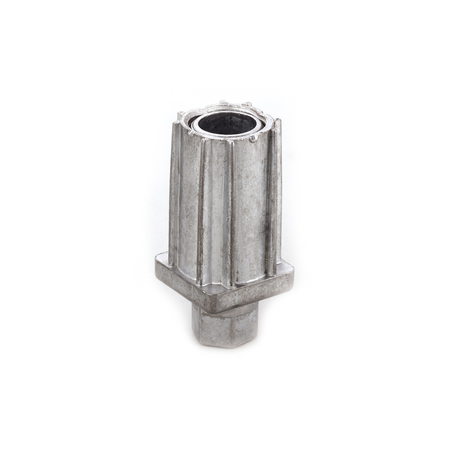
When horizontal force strikes a machine frame, the energy travels downward into the support components. Understanding exactly how these components break under stress allows you to design safer systems. We have investigated hundreds of failures, and they almost always follow specific patterns.
The most vulnerable point of any threaded support is the minor diameter—the solid core of the stem inside the thread grooves. Shear force acts directly across this cross-section. When horizontal force pushes the top of the machine, the floor resists at the base. This opposing action creates a bending moment. The threaded stem acts as a lever, and the point where the stem enters the equipment chassis becomes the fulcrum. If the lateral force exceeds the material's yield strength, the stem bends permanently or snaps clean off at the thread root.
Lateral sway does not just bend the stem; it forces the threaded rod to lever violently against the internal threads of the mounting bracket or tapped hole. This prying action concentrates immense pressure on just one or two thread pitches. Over time, or during a sudden impact, this pressure deforms the internal threads. The threads strip out, the hole elongates, and the support drops out of the chassis. We often see this when thin sheet metal is used for the mounting base.
The connection point between the support and the frame dictates overall stability. Lateral load-slip behavior describes how this joint reacts under horizontal tension. If you install a Furniture Leg into a low-density material like particleboard or thin sheet metal, the joint lacks the density to hold the fastener tight. Under side load, the mounting joint slips. The fasteners loosen, the mounting plate shifts, and the entire assembly pulls out of the frame.
Before a steel stem snaps, the base often loses its grip on the floor. Every base material has a specific friction coefficient against concrete, tile, or epoxy. When the lateral force exceeds this friction threshold, the base slides uncontrollably. If the base catches on an uneven floor joint while sliding, or if the lateral force is applied high up on the equipment, the center of gravity shifts outside the footprint. The equipment tips over, causing massive damage.
Many supports feature a ball-and-socket swivel joint to accommodate uneven floors. This articulation provides flexibility but introduces a mechanical weak point. The neck of the ball stud is significantly narrower than the main threaded stem. Sudden lateral impulses—like a forklift bumping a conveyor—concentrate extreme shear stress directly on this narrow neck, frequently causing it to shear off instantly.
Selecting the right component requires mathematical evaluation and material science, not just reading a static weight chart. You must match the physical properties of the mount to the dynamic realities of the environment. Here is how we evaluate them in the field.
You cannot evaluate shear risk without calculating the bending moment. The formula is straightforward: Force multiplied by Distance. The "Force" is the anticipated lateral load, and the "Distance" is the exposed length of the threaded stem (the extension height). A 100 lb lateral force applied to a stem extended 1 inch creates a 100 in-lb bending moment. If you extend that same stem to 4 inches, the bending moment quadruples to 400 in-lb. You must specify a stem diameter thick enough to resist the maximum calculated bending moment at full extension.
Material selection dictates shear resistance. 1045 Carbon Steel offers a significantly higher shear modulus and tensile strength compared to 304 Stainless Steel or extruded aluminum. For high-impact environments, hardened steel stems are mandatory. Furthermore, the mating joint member must match this strength. Bolting a heavy-duty steel plate to a solid steel machine frame provides excellent lateral resistance. Screwing that same plate into soft wood or thin-gauge aluminum guarantees joint failure under side load.
Material Type | Relative Shear Strength | Best Application Environment |
|---|---|---|
Zinc-Plated Mild Steel | Low to Moderate | Light duty, static loads, office environments. |
304 Stainless Steel | Moderate | Washdown areas, food processing, moderate vibration. |
1045 Carbon Steel | High | Heavy machinery, high impact, robotic cells. |
The footprint of the support interacts directly with the floor material to resist sliding. A larger base diameter distributes vertical weight but does not inherently stop lateral movement without friction. Integrating elastomer pads—such as NBR rubber or polyurethane—drastically increases static friction. The rubber grips the concrete or epoxy, forcing the lateral energy to be absorbed by the frame rather than allowing the machine to skate across the floor.
Lateral stability depends heavily on where you place the supports relative to the equipment's center of mass. A top-heavy machine with a narrow stance tips easily under minor side loads. Spreading the mounting points as wide as possible increases the footprint, lowering the center of gravity relative to the pivot point. This wide stance maximizes the lateral force required to initiate a tipping event.
Not all supports handle horizontal stress equally. Categorizing components by their structural design helps you match the hardware to the application. We break them down into three main categories.
These components consist of thin threaded stems (often M8 or M10) attached to plastic or thin metal bases. They excel in static environments where gravity is the only force at play. However, their limitations become obvious under dynamic conditions. A simple push from a heavy cart will bend the stem. They offer minimal shear resistance and present a severe risk of joint-slip if the equipment experiences cyclic side-sway.
When specifying a Leveling Foot for industrial use, mass and material density matter. These units feature thickened stems ranging from M16 to M30, machined from solid carbon or stainless steel. The solid steel bases provide a rigid foundation. Fine thread pitches offer tighter engagement with the mounting bracket, reducing slop and lateral deflection. This mass absorbs operational vibration and resists the bending moments generated by heavy workbenches and packaging equipment.
When friction and stem thickness are not enough to guarantee safety, you must bypass the friction limitation entirely. Floor-anchored mounts feature teardrop or flanged bases with pre-drilled holes. By driving wedge anchors or concrete screws through these flanges, you physically lock the equipment to the floor. This design transfers all lateral loads directly into the concrete substrate. They are mandatory for robotic cells, high-vibration stamping presses, and any equipment installed in active seismic zones.
Even the strongest hardware fails if installed incorrectly or integrated poorly into the overall structural design. Avoid these common implementation errors to ensure long-term stability on the job site.
Calculate the exact extension height needed before ordering. Do not guess. Measure the floor deviation.
Select the appropriate stem diameter. Base this on the calculated bending moment, not just the vertical weight.
Install structural spacer blocks if the floor is severely uneven. This prevents over-extending the threaded stem.
Apply high-strength thread-locking compounds. Do this on all jam nuts in high-vibration environments.
Perform regular torque audits. Check the mounts every six months to ensure nothing has backed off.
The most frequent installation error is over-extending the threaded stem to compensate for severely uneven floors. As previously established, extending the stem increases the lever arm, multiplying the bending moment exponentially. The strict rule of thumb is to keep the exposed thread as short as possible. If a machine requires three inches of lift to sit level, do not use a four-inch stem extended to its maximum limit. Instead, install a solid structural spacer block under the frame and use a shorter stem to handle the final micro-adjustments.
Never force support components to carry 100% of the lateral shear alone. They are designed to level equipment, not to act as the primary lateral force resisting system. You must design system-level resistance into the machine frame. Incorporate structural cross-bracing, heavy-duty gussets at right angles, or frame-to-wall tie-backs. These structural additions distribute horizontal forces across the entire chassis, drastically reducing the localized shear stress on any individual floor mount.
Relying exclusively on static load charts for dynamic applications guarantees failure. A component rated for 5,000 lbs static vertical load might yield under 500 lbs of lateral impact. You must apply a safety factor when calculating required capacities for environments with lateral movement. A safety factor of 2x to 4x the static weight is standard practice for dynamic loads. Always request dynamic shear test data from the manufacturer rather than trusting basic vertical crush ratings.
High-vibration environments cause threaded connections to settle and loosen. Lateral loads create micro-movements that force locking nuts (jam nuts) to back off over time. Once the jam nut loosens, the stem wobbles inside the mounting bracket, accelerating thread wear and increasing the risk of shear failure. Mitigate this risk by applying high-strength thread-locking compounds during installation. Additionally, mandate regular torque audits in your maintenance schedule to ensure all jam nuts remain tightly secured against the frame.
A high-strength anchored mount is only as strong as the floor holding it. Bolting a massive steel flange into weak, crumbling concrete provides a false sense of security. Under extreme lateral load, the concrete will spall, and the anchor will pull out long before the steel mount fails. Always evaluate the concrete compressive strength (PSI) and verify the anchor pull-out ratings before relying on floor-anchored systems to resist heavy horizontal forces.
Audit your equipment's center of gravity and calculate the maximum potential lateral forces, accounting for both cyclic side-sway and sudden impulse impacts.
Install solid structural spacer blocks under frames on severely uneven floors to minimize the exposed thread length and reduce the bending moment.
Integrate structural cross-bracing or frame-to-wall tie-backs on all high-vibration machinery to distribute horizontal forces away from the floor mounts.
Request verified dynamic shear-strength data and material yield specifications from component manufacturers before committing to a bulk order.
A: Static load capacity measures the maximum downward vertical weight a component can support without crushing. Lateral load capacity measures the maximum horizontal force it can withstand before bending, shearing, or slipping sideways. Components handle vertical loads easily but fail quickly under lateral stress.
A: Standard components withstand very little lateral force. Depending on the stem diameter and extension height, a standard leg might bend or snap under just 50 to 200 lbs of horizontal pressure, even if its vertical rating exceeds 1,000 lbs.
A: Most manufacturers prominently advertise vertical static loads but rarely publish dynamic shear strength ratings. You must specifically request shear data, bending moment limits, or material yield strength specifications from the engineering department before purchasing for dynamic applications.
A: Extension height acts as a lever arm. The further you extend the threaded stem out of the mounting bracket, the greater the bending moment generated by any horizontal force. Keeping the exposed thread short exponentially increases lateral stability and prevents bending.
A: Rubber pads increase base friction, preventing the equipment from sliding across the floor. However, they do not reduce stress on the stem. By stopping the base from moving, the pad actually forces the threaded stem to absorb the full bending moment of the lateral impact.
A: Joint-slip occurs when the mounting hardware shifts or loosens under horizontal tension. High-density substrates like thick steel hold fasteners tightly, resisting slip. Low-density substrates like particleboard allow fasteners to wallow out, causing the joint to fail under side load.
A: You should use structural cross-bracing whenever equipment experiences continuous vibration, cyclic side-sway, or heavy lateral impacts. Leveling feet level the machine; cross-bracing provides the actual system-level resistance needed to distribute horizontal forces safely across the frame.